DC Circuits
We began by exploring DC circuits in this chapter, connecting batteries in series and parallel. My son learned to use the multimeter to measure voltage and had fun putting together enough batteries to make a powerful 18V battery pack. We also did the "Potentiometer as a Rheostat" activity and I learned why potentiometers are labeled as 10K or 5K or whatever, referring to their maximum resistance.
AC Circuits
We quickly moved on to alternating current because this was most interesting to us. It was a big grey area to me and I was interested in demystifying house mains electricity and learning how to handle it safely.
Stepdown Transformer

It begins with this lesson. To find an AC stepdown transformer we had to take a trip to the Lower East Side Ecology Center and identify a piece of electronics old enough to contain a useful transformer. They were able to guide us to a dual tape deck, about 30 years old, that ended up containing a wealth of useful components.
In making it we learned more about mains cords in this clear video. We watched various videos to help with understanding induction, like this.
The recommended transformer is a center-tapped 12-0-12 type to give a 6V power source and ours is slightly more complicated with two separate windings that provide ~14V on the left pair and ~28V on the right pair. You can see in the picture how I covered the primary winding pins for safety and ran the secondary pairs down to secured screws for easy access to alligator clips.
The recommended transformer is a center-tapped 12-0-12 type to give a 6V power source and ours is slightly more complicated with two separate windings that provide ~14V on the left pair and ~28V on the right pair. You can see in the picture how I covered the primary winding pins for safety and ran the secondary pairs down to secured screws for easy access to alligator clips.
Make a Transformer

This lesson showed us the basic arrangement of windings and iron bars to create inductive power transfer. It is obviously not efficient but with 14V input to the primary side about 1.5V is produced on the secondary side. The number of windings on the primary and secondary sides are 600 and 300, respectively, mostly done by me despite my son's promise that he would do a lot of it.
AC Induction Motors
Here we got sidetracked into learning how motors work that are powered directly by AC current. We had some motors sitting around from things we've found and taken apart and started playing with them to understand them better. Clockwise from upper left, they come from 1) a weed whacker, 2) a dual window fan, 3) a humidifier, 4) an Oster blender, and 5) another blender.
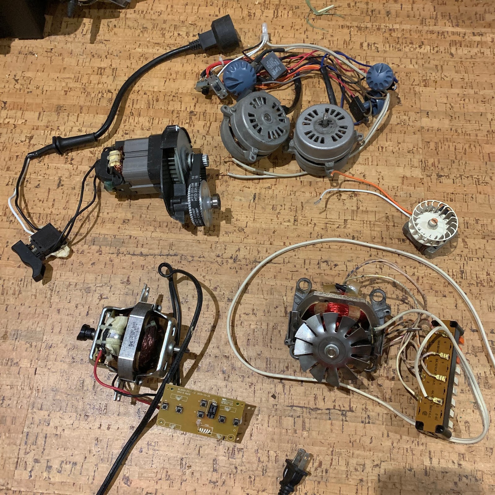
Before getting the stepdown transformer we had clamped the weed whacker and one of the blenders in a table vise and connected them directly to an outlet and switched them on, producing a frightening roar of power. While it was impressive to see the awesome power contained in these devices unleashed it was better to be able to run them on 28V from the transformer, a much safer speed. The little humidifier motor is wonderfully calm, however, and purrs along nicely at a full 120V. So to understand how AC motors work this Matthias Wandel video was very helpful. Jeremy Fielding also has a really informative series of videos explaining how different types of DC and AC motors work.
Learning About Oscilloscopes
I had never used an oscilloscope and at this point I was thinking one would be really useful to visualize the different between AC and DC power. Benchtop oscilloscopes are quite expensive but after some research I found this cheap oscilloscope by Etepon that has served us well so far.

Half Wave Rectifier
This lesson comes later in the textbook experiments but is a great way to see what happens when you use a diode to block the flow of current in one direction. The circuit has a diode, and a 10K ohm resistor to stabilize the current with a load (I had to do some research to learn the importance of that) both in series. With the probes across the resistor you can see that only the positive current is detected and the negative flow becomes a flat line!


Full Wave Bridge Rectifier
I had seen many Electroboom videos including his signature FULL WAVE BRIDGE RECTIFIER circuit he gets so excited about, as in this video. It turns out this circuit is basic in so much of how we use electricity in our daily lives because it converts AC current to DC current in the form of all the adapters we plug into our outlets to power countless devices, from computers to clocks to toys. And it is easy to make by following this lesson.


Here we arranged four diodes to produce the the signal you see, in which the negative current comes out as positive current, coming close to being a representation of direct current. One problem with it is its inefficiency, as the voltage is dropping to zero 120 times per second, so after some research online I learned about the technique in the next section.
Capacitor To Smooth Current

Adding an electrolytic capacitor across the output smooths the voltage variation because it is quickly being charged and discharging the energy smoothing out the dip to zero, so with a 1000µF capacitor the smoothing almost reaches a flat line with only a resistor as load. Videos like this one helped me understand how this works.
Current Ripple

AC Adapter Project
At this point I realized I had the tools and enough knowledge to make my own AC adapter. We needed a soldering fume extractor so I made one! It powers a 12V .16A DC computer fan with 22V from the full wave bridge rectifier. Overpowering the fan motor made it more effective at pulling the smoke in but it also would likely make the motor wear out quickly. It does get pretty warm after some use, but more about that in the next section.

What was really exciting is that most of the components are reused. The transformer and power cord came from a humidifier, the diodes and capacitor came from the tape deck, the switch from an old record player, and the fan came from a PC.

Project Fail
As mentioned, it's not great to power a 12V rated motor at 22V for very long. My son surprised me with a birthday present of a real fume extractor (he will enjoy it, too) and it turns out these fans are designed in a certain way.

This fume extractor first of all has a bigger rotor than a computer fan to handle more current. And it is powered with 110V AC! So it's not even a DC motor. With this more effective fume extractor now I have to find another use for my homemade 22V DC power supply.

Sensitive Audio Detector

This is an amazing tool for experiencing current flow through another sensory input. You can hear that AC current cycles 60 times per second (60Hz) by hearing that all AC currents are at the same pitch! And DC currents can be detected, too, by listening to DC motors. These are all at different frequencies, depending on their size. Small motors sound like mosquitoes!
Unfortunately I can't provide a sample of the sound produced by this audio detector for lack of the proper dongles for any Mac devices (boo), but what you hear is a beautiful, rich hum.
Golden Age of Hacking Electronics
The All About Circuits digital textbook that provided so much guidance for our experiments was first published some 20 years ago, and some of the references really show how dated it is. One experiment, a digital oscilloscope, requires a PC with Windows 3.1, a long gone OS. At some point it hit me how much electronics have changed over the last two decades, to the point where we are at a turning point in the possibilities for tinkering with electronics that this curriculum depends on. Rather than re-explaining here, I'll just provide my Twitter thread:
I just went to the Lower East Side Ecology E-Waste warehouse to get an old clock radio for $5. I need a ~6V stepdown transformer for a project. I’ve been thinking, this is the golden age for hacking and DIY electronics. 1/n pic.twitter.com/1nFxQ68FIc— Erik Nauman (@openblackboard) August 20, 2019

No comments :
Post a Comment