
After some research it turned out to be a vacuum fluorescent display, specifically an NEC FIP4B9E, commonly used in older microwaves, stereos, clocks, and other electronics. I found a couple resources really helpful in understanding how they work and how to connect them in a circuit; this blog post (I also corresponded some over email with it's author, Michał Słomkowski, who was very helpful) and this video tutorial.
Lighting Up the Anodes
The anodes are the segments themselves, coated with phosphor that lights up green or orange when 20-30 volts AC or DC is applied. The above blog post will explain the whole picture, but the short version for this particular display is that the filament pins on either end take 3.3V, and the grid pins and anode pins take 20V. See the post for how to figure out which are grid and which are anode pins as well. I now know that while the grid pins can be connected directly to the 20V source the anode pins need a resistor each in the range of 22-47K ohms to preserve the anodes over time and even out the voltage distribution.
Before I had salvaged the original transformer that had powered it in the microwave with one 3.3V secondary winding and one 20V secondary winding I supplied about 4 V DC from my bench power supply and 28 V from another transformer. You can see the filaments glowing, which is pretty but a sign they are getting too much voltage.

Controlling the Anodes
Next step was to turn individual grids on and off to control each digit separately. I used an Arduino and connected to a grid pin through a transistor with its emitter connected to the Arduino's ground (Arduino pin to base, collector to grid pin). Setting the Arduino pin high pulls the grid pin to ground, which causes it to repel the electrons being emitted from the filament, so they don't reach the anodes and light them up, all of which is explained in the above video. Conversely setting a grid and whichever anodes you want lit to low will allow voltage to the grid pin, attracting the electrons from teh filaments, and on to the anodes, lighting them up. Any anodes set low will display across all digits that have their corresponding grid pin set low, which means the only way to make different digits display different numbers is by multiplexing. I found a delay of 5 milliseconds between each digit to be fast enough to not see a flicker, though the digits are a little dimmer than when not multiplexing. Later I added a potentiometer to vary the delay so you can see the multiplexing effect when slowed down.


Building the First Circuit

I decided to be ambitious and power the display and an Adafruit Metro Mini with the transformer I salvaged from the original microwave board. I used a salvaged rectifier and 640 mF capacitor to run a DC 20V line off the 20V AC winding to a buck converter, which dropped the voltage down to 6.5V for the microcontroller. To control all the grids and anodes with the microcontroller, I connected each pin through two Darlington transistor arrays (NTE2018), and connected the array ground pin to the microcontroller ground. I also added a 100K potentiometer and an SPDT switch that could supply 3 states. I swear all this worked properly on a breadboard, nothing seemed wrong. I checked things as I soldered it together as best I could and it seemed to be coming together well, but when it was all together suddenly the transformer was behaving strangely, supplying only 10V at the 20V winding and getting very hot. I searched in vain for a short or some connection I had made differently than on the breadboard but could find nothing. So I salvaged all the parts and went back to the drawing board.


The Second Circuit Worked!
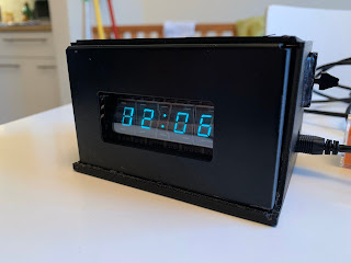
This time I decided to power the microcontroller over 5V USB, and power the display using 5V off the microcontroller boosted to 20V with a buck booster. The filament is powered from the microcontroller's 3.3 V pin. Because the filament is powered by DC there is a visible voltage drop across the anodes, resulting in a ghosting effect on the left side. When the filament is powered by AC the alternating direction cancels out the visibility of the voltage drop.

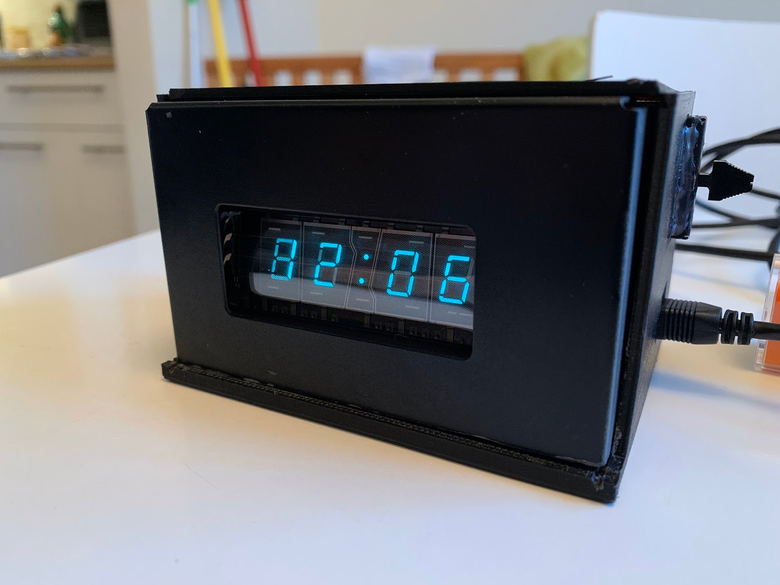
One thing I decided to have it do is display 12:00
on startup and blink the time from there. That's becuase
I remember electronics doing that, getting reset to 12:00
whenever they lost power.

Beautiful!
I drew up a rough diagram of the circuit. Hopefully it is clear that the grid pins initially showed resisters on them and they are now drawn through as they don't need them.
On to More Displays!
Now that I've got the basics down I'm tackling this more ambitions display from an old Onkyo entertainment system.

I contemplated connecting it up to a microcontroller as well, but decided against it because of the number of grid and anode pins, 16 and 40 respectively. The arrays of 40 dots were used to display letters scrolling across the display, which would be really cool. But it will be beautiful just to turn on and off. And since all I'm powering is the display I'm able to use the 120 to 3.3/20V transformer to power it since there's no microcontroller to confuse me.

No comments :
Post a Comment