
Verify pin configuration
First I figured out the pin configuration by connecting a 3V battery pack across the end pins to power the filament, then from a 20V DC power supply I connected the negative lead to an end filament pin and the positive lead to a breadboard positive rail, then from the rail to two separate rows with 22k ohm resistors, and from those resistors to jumpers which I touched on various inner pins to determine which set powered the grids and which set the segments. It turned out the 16 grid pins are on the right.
Breadboard Power Circuit
I set the vfd pins into a breadboard and connected all the grid and segment pins to the powered rail through 22k ohm resistors.


This vfd has a plastic veneer in a sort of ochre color that gives the anodes an interesting tint.

Solder On Perfboard

All pins soldered onto a perfboard, with foam risers that supported it off the original circuit board glued back in underneath. Ribbon cables from old vcrs and stereos are soldered in that will be routed to transistor arrays.
Add Resistors

I accidentally ordered 1/2 watt resistors that are too wide to fit next to each other. So I stood them up and staggered the pins.

I laid out the Darlington transistor arrays to align their pins with the ribbon cables.
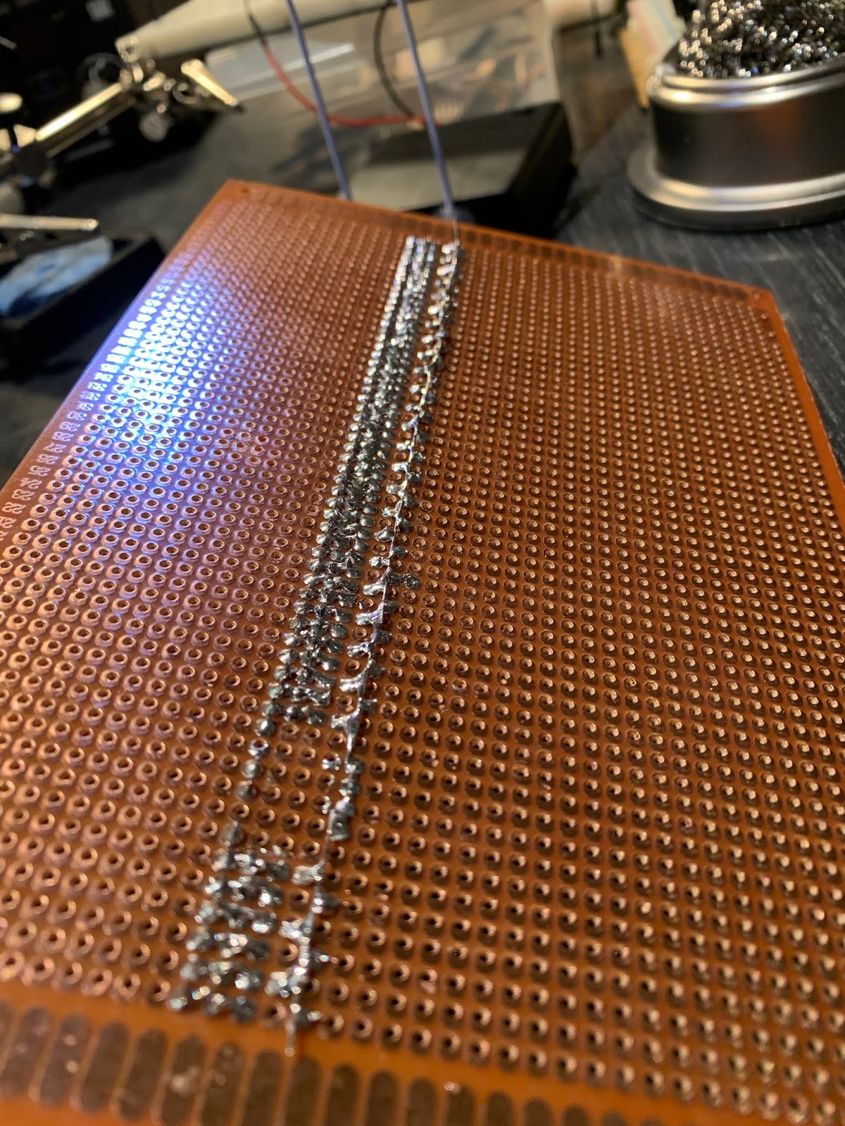
The solder line on the right shows the staggered resistor pins, tied together with wires run between them.
Solder On Transistor Arrays

The transistor arrays are connected to the ribbon cables, and all of their common GND pins connected together.


Careful soldering

Testing. Still works!
Transfer Power Circuit To Teensy and Buck Booster
I connected the filament pins to 3.3V and GND pins on the Teensy, and 3.3V and GND to a buck booster, and set the booster out voltage to 20V. The negative out goes to the filament, and the positive goes to the power rail with all the resistors. Good to see this working because this step didn't work on a previous vfd for some reason.


Soldering In the Teensy
This vfd has so many pins for the control circuit, 53 counting grid and segment pins, I have to use the surface mount I/O pins underneath. The surface mount headers I got were not the same spacing unfortunately so I had to cut off pairs and set them in a perf board piece to solder them in. Fortunately it worked.


Now with the surface mount headers poking through I'm soldering on ribbon jumpers to them and running that around the front. Another careful procedure.

Eight pins connected, tested and it's working!
Remaining Teensy Pins Soldered

Some interesting wire bundles from various old electronics.


Soldering to surface mounted headers was very challenging. This is a very fragile point and may have to be repaired soon. Already one wire has to be wiggled to connect properly.
Already the animating possibilities are so fun!

No comments :
Post a Comment