
Salvaging the Display

Figuring Out The Pins

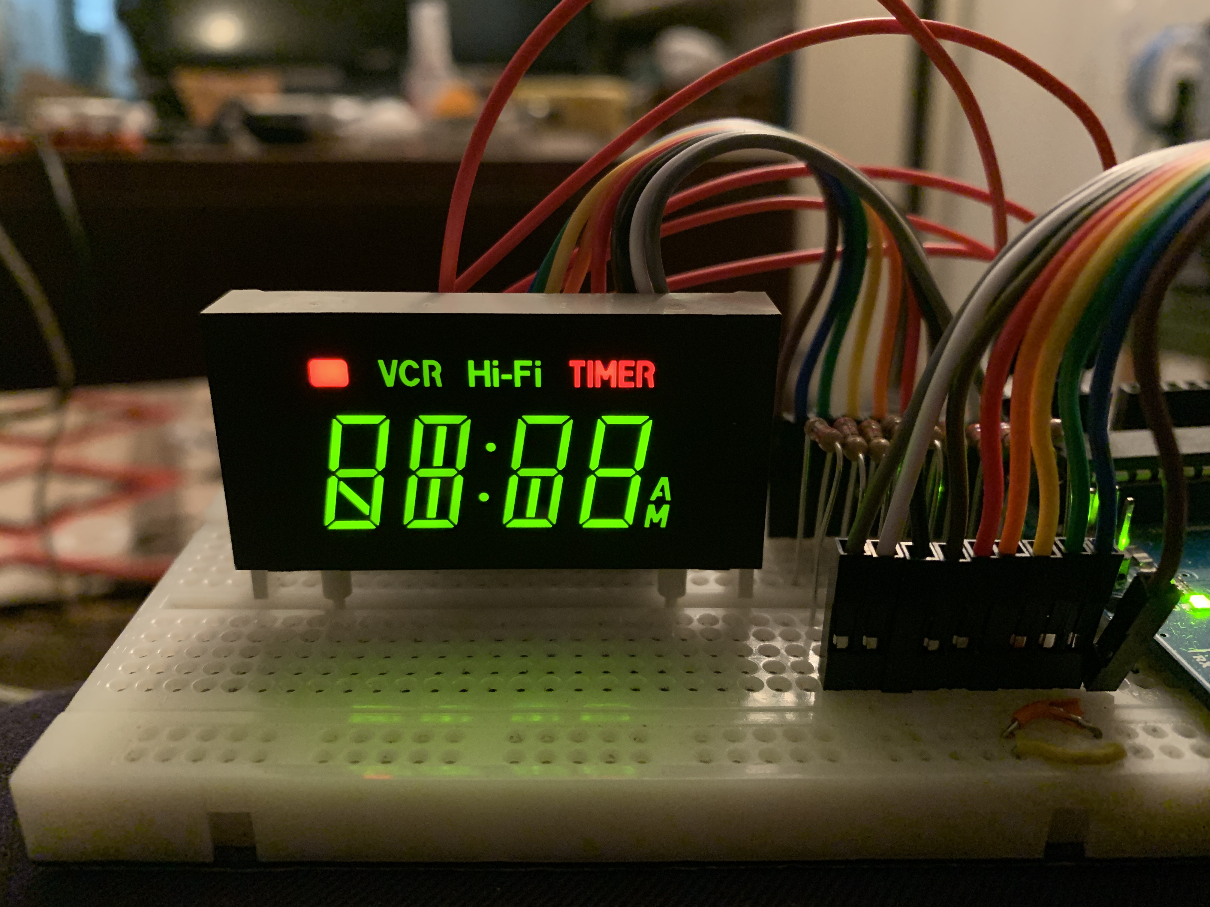
Second thing is digits can encompass more than just (alpha)numerical segment sets. On this one it turns out the 5th grid pin controls only the red rectangle at top left and the word TIMER on the right, also red.
It's very helpful to make a diagram of the pins to write down what each pin connects to. Here I label what the 5 digit sections are, and clarify for myself that each section can have up to 10 different parts lighting up. One digit, the 5th, only has 2 things to light up. Figuring out which cathode pin is for each segment in each digit is not necessary at this time, but it could be helpful in the software stage later depending on what you want to do with the display.


Move the circuit to an Arduino

Time to code!
The first thing to do in Arduino code is get all the segments to light up. Once the pin variables are defined I put the pin names in an array. This will make it easier to create patterns through loops in various functions. The first place to use the array in a loop is in setup, to set the pinMode for all the segments and digits. The for loop looks more complicated than it should, but simplest way to get the number of elements in an array in Arduino is to divide the array by the size of one element in the array because of how C works. (See here for more, scroll to bottom)One more thing about this code, since this 7-segment is common anode that means any segment we want to light up has to go LOW while the common pin for its digit goes HIGH. Any segment we want to turn off has to go HIGH so there is no voltage potential between the segment pin and the common pin.
//common anode 7-segment
const int seg1 = 2; //cathodes
const int seg2 = 3;
const int seg3 = 4;
const int seg4 = 5;
const int seg5 = 6;
const int seg6 = 7;
const int seg7 = 8;
const int seg8 = 9;
const int seg9 = 10;
const int seg10 = 11;

const int d1 = A1;  //anodes
const int d2 = A2;
const int d3 = A3;
const int d4 = A4;
const int d5 = A5;

//put the segments in an array to use more easily later
const int segments[] = {seg1, seg2, seg3, seg4, seg5, seg6, seg7, seg8, seg9, seg10};
const int digits[] = {d1, d2, d3, d4, d5};
void setup() {
  //use the array to set them OUTPUT
  for (int i = 0; i < sizeof(segments) / sizeof(segments[0]); i++) {
    pinMode(segments[i], OUTPUT);
  }
  for (int i = 0; i < sizeof(digits) / sizeof(digits[0]); i++) {
    pinMode(digits[i], OUTPUT);
  }
}

void loop() {
  //use the array to set them all LOW
  //segments go LOW for on because they are cathodes
  for (int i = 0; i < sizeof(segments) / sizeof(segments[0]); i++) {
    digitalWrite(segments[i], LOW);
  }
  //set the digits to HIGH, since common anode
  for (int i = 0; i < sizeof(digits) / sizeof(digits[0]); i++) {
    digitalWrite(digits[i], HIGH);
  }
}
What you get is the same thing as when all pins were connected to the battery, which as you can see, leaves 2 segments very dim because of the red segments.

In my experience this doesn't usually happen, but it's not hard to create the multiplexing effect to even out the LEDs. We will add a delay in the digit for loop so they turn on and off really fast.
Here is the updated code in loop():
void loop() {
  //use the array to set them all LOW
  //segments go LOW for on because they are cathodes
  for (int i = 0; i < sizeof(segments) / sizeof(segments[0]); i++) {
    digitalWrite(segments[i], LOW);
  }
  //set the digits to HIGH, since common anode
  for (int i = 0; i < sizeof(digits) / sizeof(digits[0]); i++) {
    digitalWrite(digits[i], HIGH);
    delay(3);
    digitalWrite(digits[i], LOW);
  }
}
And here is the better result. Each of the 5 grids is blinking on and off so fast we perceive it as all lit up at once. Cool!
Making Useful Functions

void loop() {
  on();
  off();
  delay(1000);
}

void on() {
  for (int j = 0; j < 66; j++) {
    for (int i = 0; i < sizeof(segments) / sizeof(segments[0]); i++) {
      digitalWrite(segments[i], LOW);
    }
    for (int i = 0; i < sizeof(digits) / sizeof(digits[0]); i++) {
      digitalWrite(digits[i], HIGH);
      delay(3);
      digitalWrite(digits[i], LOW);
    }
  }
}

void off() {
  for (int i = 0; i < sizeof(segments) / sizeof(segments[0]); i++) {
    digitalWrite(segments[i], LOW);
  }
  for (int i = 0; i < sizeof(digits) / sizeof(digits[0]); i++) {
    digitalWrite(digits[i], LOW);
  }
}
Add buttons for interactivity


- a pin declaration for each
- setting pinMode to INPUT_PULLUP for each (note this pulls each button HIGH by default so when it is pressed it will register as LOW)
- creating a boolean to monitor when each is pressed and report that to the Serial Monitor.
const int buttonLeft = 13;
const int buttonRight = 12;
boolean leftPressed = true;
boolean rightPressed = true;
//this goes in setup
  pinMode(buttonLeft, INPUT_PULLUP);
  pinMode(buttonRight, INPUT_PULLUP);
  Serial.begin(9600);
//and here is loop
void loop() {
  leftPressed = digitalRead(buttonLeft);
  rightPressed = digitalRead(buttonRight);
  Serial.print("left: ");
  Serial.println(leftPressed);
  Serial.print("right: ");
  Serial.println(rightPressed);
  delay(1000);
}
...and check the serial monitor while pressing each one. When not pressed each should report 1, and when pressed it should report 0.
Make the buttons do something!
void loop() {
  checkButtons();
  showDigit();
}

int whichDigit = 0; //start at digit 0
void checkButtons() {
  leftPressed = digitalRead(buttonLeft);
  rightPressed = digitalRead(buttonRight);
  if(!leftPressed && whichDigit > 0) { //if left button goes LOW and digit is above 0 decrease digit
    whichDigit--;
    delay(500);  //bad debounce (there's a better way that's more complicated)
  }
  if(!rightPressed && whichDigit < 4) { //if right button goes LOW and digit is below 4 increase digit
    whichDigit++;
    delay(500);
  }
}

void showDigit() {
  off();
  digitalWrite(digits[whichDigit], HIGH); //from the digits array turn on the current one
  for (int i = 0; i < sizeof(segments) / sizeof(segments[0]); i++) {
    digitalWrite(segments[i], LOW);
  }
}
A Simple Game
//common anode 7-segment
const int seg1 = 2; //cathodes
const int seg2 = 3;
const int seg3 = 4;
const int seg4 = 5;
const int seg5 = 6;
const int seg6 = 7;
const int seg7 = 8;
const int seg8 = 9;
const int seg9 = 10;
const int seg10 = 11;

const int d1 = A1;  //anodes
const int d2 = A2;
const int d3 = A3;
const int d4 = A4;
const int d5 = A5;

const int buttonLeft = 13;
const int buttonRight = 12;
boolean leftPressed = true;
boolean rightPressed = true;

//put the segments in an array to use more easily later
const int segments[] = {seg1, seg2, seg3, seg4, seg5, seg6, seg7, seg8, seg9, seg10};
const int digits[] = {d1, d2, d3, d4, d5};

//for blip position
int xpos = 0;
int ypos = 0;

//for moveBlip
int blipWaitTime = 1000;
double lastBlipMove = 0;

//for checkButtons
int whichDigit = 0;
int buttonDebounce = 500;
double lastPress = 0;

void setup() {
  //use the array to set them OUTPUT
  for (int i = 0; i < sizeof(segments) / sizeof(segments[0]); i++) {
    pinMode(segments[i], OUTPUT);
  }
  for (int i = 0; i < sizeof(digits) / sizeof(digits[0]); i++) {
    pinMode(digits[i], OUTPUT);
  }
  pinMode(buttonLeft, INPUT_PULLUP);
  pinMode(buttonRight, INPUT_PULLUP);
  Serial.begin(9600);
  randomSeed(A0);
}

void loop() {
  checkButtons();
  showPlayer();
  showBlip();
  moveBlip();
  checkHit();
}

void checkHit() {
  if(ypos == 2 && xpos == whichDigit) {
    for(int i = 0; i<4; i++) {
      on();
      off();
      delay(200);
    }
  }
}

void checkButtons() {
  leftPressed = digitalRead(buttonLeft);
  rightPressed = digitalRead(buttonRight);
  //better debounce that only changes the digit if certain amount of time has passed
  if (!leftPressed && whichDigit > 0 && millis() > lastPress + buttonDebounce) {
    whichDigit--;
    lastPress = millis(); //reset the last time pressed
  }
  if (!rightPressed && whichDigit < 3 && millis() > lastPress + buttonDebounce) {
    whichDigit++;
    lastPress = millis();
  }
}
//these are coordinates for x and y positions of the blip so it can fall down one of the 4 digits
//the first of each pair is the digit number, second is the segment number
const int blipCoordinates[4][3][2] = {
  {{4,0},{0,5},{0,4}},
  {{0,8},{1,5},{1,4}},
  {{3,7},{2,5},{2,4}},
  {{4,1},{3,5},{3,4}}
};

void showBlip() {
  off();
  digitalWrite(digits[blipCoordinates[xpos][ypos][0]],HIGH);
  digitalWrite(segments[blipCoordinates[xpos][ypos][1]],LOW);
  delay(3);
}
//moves the blip by changing ypos after time elapsed without blocking other things with a delay
void moveBlip() {
  if(millis() > lastBlipMove + blipWaitTime) {
    ypos++;
    lastBlipMove = millis();
    if(ypos > 2) {
      ypos = 0;
      xpos = random(4);
    }
  }
}

void showPlayer() {
  const int playerSegments[] = {seg3, seg4, seg5, seg7};
  off();
  digitalWrite(digits[whichDigit], HIGH);
  for (int i = 0; i < sizeof(playerSegments) / sizeof(playerSegments[0]); i++) {
    digitalWrite(playerSegments[i], LOW);
  }
  delay(5);
}

void on() {
  for (int j = 0; j < 20; j++) {
    for (int i = 0; i < sizeof(segments) / sizeof(segments[0]); i++) {
      digitalWrite(segments[i], LOW);
    }
    for (int i = 0; i < sizeof(digits) / sizeof(digits[0]); i++) {
      digitalWrite(digits[i], HIGH);
      delay(3);
      digitalWrite(digits[i], LOW);
    }
  }
}

void off() {
  segmentsHigh();
  digitsLow();
}


void segmentsHigh() {
  for (int i = 0; i < sizeof(segments) / sizeof(segments[0]); i++) {
    digitalWrite(segments[i], HIGH);
  }
}

void digitsLow() {
  for (int i = 0; i < sizeof(digits) / sizeof(digits[0]); i++) {
    digitalWrite(digits[i], LOW);
  }
}
There are plenty of things that can make this game better, like the speed of the blip is quite slow, so I will increase that. There could be levels of difficulty, like after 10 times avoiding the blip it can go faster. It would be a more difficult thing to do but there could be more blips to avoid. But the basic hardware is done, so next I want to make it permanent by soldering it all together.
Solder it together


No comments :
Post a Comment